One of my absolute favorite classes during graduate school was 2.720, Elements of Mechanical Design. The course is an intensive education in machine design, engineering design, manufacturing, and precision.
The final project of the class was the analysis, design, and fabricating of a small desktop lathe that can cut steel to an accuracy of .002”. All students were provided with a CAD assembly containing an example lathe, and a box of supplied parts including bearings, castings, and fasteners. There was a catch though. Many aspects of the CAD were intentionally incorrect, and if built without thorough analysis, would only show up after being put together (My group and I found all the “traps” but one!)
This format allowed each student group to analyze, design, build, and test a lathe during the semester.
First, my group and I started on the spindle assembly.
 |
|---|
| The spindle subassembly |
The design consisted of a steel spindle shaft with a press fit taper bearing installed into an aluminum housing, with an axially “free” taper bearing opposed, preloaded by a Belleville washer.
 |
|---|
| The free body diagram of the spindle shaft |
The analysis for the subassembly consisted of sizing the spindle shaft to minimize deflections at expected loads, correctly sizing the bearing press fit, and choosing the proper preload for the rear bearing to avoid excessive heat generation while maximizing stiffness.
 |
|---|
| Machining the spindle shaft |
Once completed, the group and I devised and performed experiments to evaluate the spindle’s stiffness, torque, and thermal performance against our functional requirements.
|  |
|:–:|
| Testing the completed spindle assembly for deflection under load |
—
|
|:–:|
| Testing the completed spindle assembly for deflection under load |
—
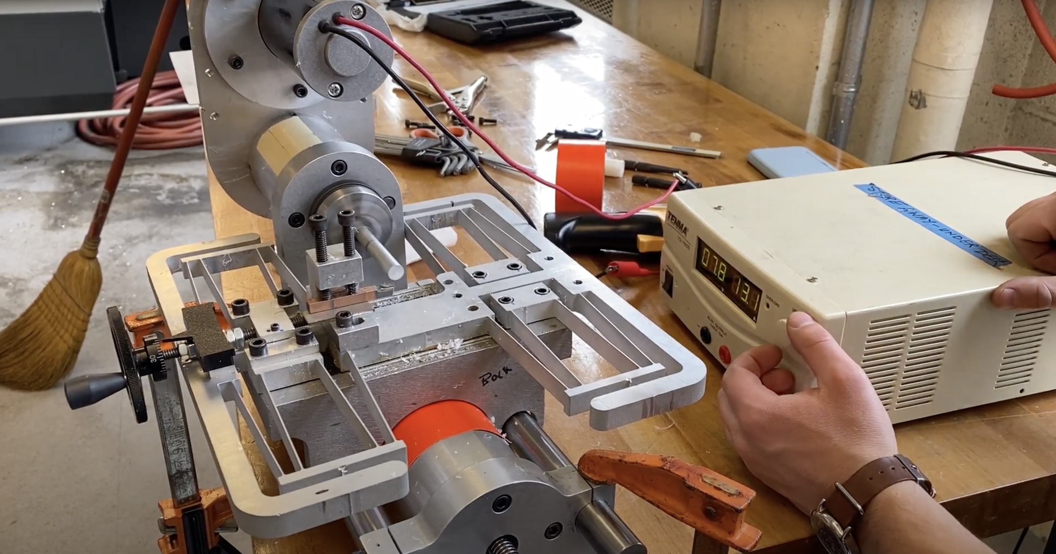
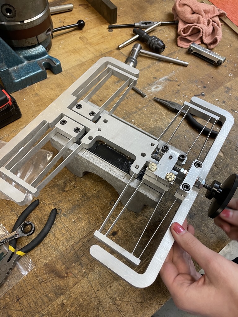
With the spindle assembly validated, it was time to work on the cross slide, or X-axis, of the lathe. The design framework established by the course staff involved a large flexure that formed the basis of the cross slide assembly. This was my first introduction to flexures, and I was absolutely fascinated by them. Using a flexure for the lathe’s X-axis allowed for flexibility in the desired direction, stiffness where needed, and precise movements all from a 2D waterjet part.
 |
|---|
| The large flexure that serves as the basis for the lathe’s cross slide |
The design of the flexure called for a 2D waterjet operation out of a sheet of aluminum, and its design and manufacturing requirements prompted the following analyses:
- Stiffness in X, Y, and Z
- Can the flexure move far enough in the desired direction without plastically deforming?
- Resonant frequencies and how they may interact with vibrations of the lathe
- Waterjet tolerances and their effect on the thickness of each rib
- Fatigue and lifetime
With a desired range of travel and stiffness in each direction, we selected the thickness of the “ribs” of the flexure and manufactured the flexure using a CNC waterjet.
|  |
|:–:|
| The large flexure that serves as the basis for the lathe’s cross slide |
—
|
|:–:|
| The large flexure that serves as the basis for the lathe’s cross slide |
—
One of the most important takeaways for machine design is creating an “error budget” for the machine. This budget specifies a certain amount of allowable deflection, and this helps inform the stiffness and construction of each subassembly and how much you can draw from your error budget. In this case, we established a mathematical model of the entire machine using homogeneous transformation matrices.
 |
|---|
| The machine represented as a stick model, deflecting under expected cutting load. |
By iterating and refining this model as we designed, constructed, and tested each assembly, we could stay on top of our allowable machine error.
There was a lot more to this project, but I just wanted to share some of the components that give a glimpse into the work that goes into machine design. One other fascinating part of the project involved the analysis and design of self-centering flat belt pulleys that other team members worked on.


